Fractional-N PLLs have been in use since the 1970s. The fractional-N division allows the resolution of the PLL output to be reduced to a fraction of the PFD frequency (as shown), where the PFD input frequency is 1 MHz. An output frequency with a resolution of hundreds of Hz can be generated while maintaining a high PFD frequency. Therefore, the N value of the fractional-N frequency is significantly smaller than the N value of the integer N division.
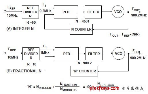
Integer-N Compared to FracTIonal-N Synthesizer
Since the noise at the charge pump is added to the output at a rate of 20 logN, the phase noise can be significantly improved. For the GSM900 system, the phase noise performance of the fractional-N ADF4252 is –103 dBc/Hz; in contrast, the integer
The phase-frequency performance of the N-divider PLL ADF4106 is –93 dBc/Hz. Another significant advantage of the fractional-N divide is the ability to improve lock time. When the PFD frequency is set to 20 MHz and the loop bandwidth is 150 kHz, the frequency synthesizer can jump 30 MHz in less than 30 s. Current base stations require the use of two PLL blocks to ensure that the LO meets the timing requirements of the transmission. Using the ultra-fast lock-in time of fractional-N division, the lock-time characteristic of the frequency synthesizer in the future will allow the replacement of two current "ping-pong" PLLs with a fractional-N PLL module.
A disadvantage of the fractional-N PLL is the high level of spurs. The composition of the fractional-N 900.2 (see Figure 7B) is that the N divider spends 80% of the time divided by 900, spending 20% ​​of the time divided by 901. The average crossover is correct, but the instantaneous crossover is wrong. Therefore, the PFD and charge pump are constantly trying to correct the instantaneous phase error. The modulator that provides the averaging function is subject to heavy digital computational activity, producing spurious components at the output. The digital noise plus the mismatch in the matching of the charge pump results in a level of spur above the allowable level of most communication standards. Fractional-N dividers have only recently made the necessary improvements to spurious performance, such as the ADF4252, allowing designers to consider using it in the traditional integer-N crossover market.
Simplify PLL design with ADIsimPLLTM
ADIsimPLLTM software is a complete PLL design package available for download from the Analog Devices website. The software has a user-friendly graphical interface and provides a complete and comprehensive guide for novice users.
Traditionally, PLL frequency synthesizer designs rely on published application notes to aid in the design of PLL loop filters. Therefore, prototype circuits need to be built to determine important performance parameters such as lock time, phase noise, and reference spurious levels. Then, “tuning†the component values ​​in the lab and repeating lengthy measurements to achieve optimization.
ADIsimPLL simplifies and improves the traditional design process. The designer first builds the PLL from the "new PLL Wizard" by specifying the frequency requirements of the PLL, selecting an integer-N or fractional-N scheme, and then selecting from the PLL chip library (model library or custom VCO) and from multiple A topology selection loop filter. This program can design loop filters and display key parameters such as phase noise, reference spurs, lock time, and lock detection performance.
ADIsimPLL is as simple and interactive as using a spreadsheet. The user can modify all design parameters such as loop bandwidth, phase margin, VCO sensitivity and component values, and the simulation results will be updated in real time. This makes it easy for users to optimize their designs for specific requirements. For example, by changing the bandwidth, the user can observe the trade-off lock time and phase noise in real time and have benchmark measurement accuracy.
ADIsimPLL includes an accurate phase noise model to reliably predict the frequency synthesizer closed-loop phase noise. Users report an excellent correlation between simulation and measurement. If desired, the designer can operate directly at the component level and observe the effects of changing individual component values.
The basic design flow using ADIsimPLL is summarized as follows:
1. Select the reference frequency, output frequency range and channel spacing
2. Select the PLL chip from the list
3. Select VCO
4. Select the loop filter configuration
5. Select loop filter bandwidth and phase margin
6. Run the simulation
7. Evaluation time and frequency domain results
8. Optimization
ADIsimPLL is suitable for integer-N or fractional-N PLLs, but cannot simulate fractional-N spurs. Phase noise prediction for fractional-N devices assumes that the device operates in "lowest phase noise" mode.
Fiber media converters can be used anywhere in the network to integrate newer technology with existing equipment to support new applications, technologies and future growth. Instead of costly, across-the-board upgrades, media converters can extend the productive life of the existing cabling as well as the active equipment.There are serious types of fiber optic media converters to fulfil with market's demand,such as 10 100 Fiber Media Converter,Media Converter 1000,etc.Foclink,a reliable supplier of fiber media converter,is always beside u 7*24.
Fiber Media Converter
Fiber Media Converter,Media Converter,Fiber Optic Media Converter,Media Converter Price
Foclink Co., Ltd , http://www.scfiberpigtail.com