The electronic mosquito killer (referred to as "electric mosquito swatter") has become a popular small household appliance in summer because of its practical effect, anti-mosquito (fly or moth, etc.), good chemical pollution, safety and hygiene. However, the manufacturer does not provide the wiring diagram, which brings certain difficulties to the maintenance.
This article refers to the address: http://
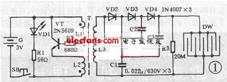
First, the working principle Bat electric "electric mosquito swatter" circuit shown in Figure 1, it is mainly composed of high-frequency oscillation circuit, triple voltage rectifier circuit and high-voltage electric shock net Dw three parts. Press the power switch SB, the high-frequency oscillator composed of the triode vT and the transformer T is electrically operated, and the 3V DC is converted into AC power of about 18 kHz, boosted by T to about 500v (measured at both ends of L3), and then passed through the diode VD2. ~VD4, capacitor c1 ~ c3 triple voltage rectification increased to about 1500V, added to the metal net Dw of the mosquito swatter. When the mosquito touches the metal mesh, the insect body causes a short circuit in the grid, which is stunned by current, arc, and burnt.
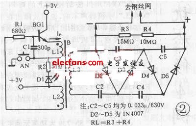
An electronic mosquito killer like a badminton racket. When there is a mosquito, use a mosquito to shoot a mosquito. The mosquito hits the mosquito net on the metal net. When the mouse clicks, the mosquito is killed by high pressure. The electronic mosquito killer The circuit principle measurement drawing is shown in the figure for reference. This is a transformer feedback type oscillator, which is boosted by the secondary voltage of the transformer and then boosted by a voltage doubler circuit composed of C1~C4 and D3~D5. More than a thousand volts of high voltage. This high voltage is connected to the ends of the interdigitated insulated mosquito nets with an interval of about 2~3mm to form a high voltage power grid. In this circuit, C3 is subjected to the highest voltage and is a storage function capacitor. Frequent charging and discharging during use, resulting in C3 is more vulnerable to damage. When a failure can not be boosted, replacing C3 can mostly eliminate the fault.
Second, the maintenance method
1. The indicator VDl is not lit. In the case of ensuring that the battery G is powered normally, the faulty multi-button switch SB has poor internal contact. The SB is a 6mm×6mm vertical miniature tact switch, which is frequently switched under the working current of 120mA. It is easy to cause the internal contact to open and open, and the new one can eliminate the fault.
2. VD1 is bright, but no high voltage is generated. At this time, the audio “å±...†sound generated by the transformer T at the moment of power-on is not heard, indicating that the oscillation circuit does not work. The cause of the fault is mostly VT damage. Replace the 2N5609 or D467 new tube to eliminate the fault. If there is no such pipe on hand, it can be replaced by 8050, 9013 NPN type triode, which works well. If the inspection VT is not damaged, and it is obviously hot after power-on, it indicates that the inner coil of the transformer T (especially the high-voltage coil L3) is broken, and it must be re-wound with the same specification enameled wire. Generally, such failure is rare.
3. Insufficient high voltage: The reason is that there are capacitors open or capacity in c1~c3, or one of the diodes vD2~vD4 is damaged, it must be detected and replaced with new ones; in addition, the battery G voltage is insufficient (vDl brightness is obviously decreased) will also cause The high voltage is not enough, just replace the new battery to eliminate the fault.
The electric mosquito swatter is the principle of the inverter. The DC power is inverted into AC power, and then double voltage is applied to generate a DC voltage of more than one thousand volts. The high voltage is used to strike the mosquito.
Repair process:
1. Use the multimeter DC voltage file to measure both ends of the battery. The normal value should be about 3 volts. Replace the battery below the normal value. Then check the battery clip for rust. If there is rust stain, wipe it with a cloth.
2. Check if the micro switch is in good contact. You can use the multimeter resistance file to measure the on/off, and you can judge whether the contact is good. If the contact is good, the LED will be illuminated. Otherwise check the LEDs.
3. Check the DC resistance of the step-up transformer. The two groups are 0 ohms and the group is about 150 ohms. This group is measured under power-on conditions and the AC voltage is around 350 volts.
4. Check the oscillating tube. The tube is available in two models: S8050, 5609. Note that the pin distribution is different. The power-on check collector (C) is 0 volts, the base (B) is 3.4 volts, the emitter (E) is 2.8 volts, and the difference between B and E is 0.6-0.8 volts.
5. Check the voltage doubler capacitor. Use the multimeter × 1 file to measure the capacitance at both ends of the circuit, the pointer is not biased to zero, it is good. If it breaks down, the pointer will be biased towards zero. After the capacitor is broken down, the electric mosquito swatter will beep when it is energized.
6. Check the boost diode. Using a multimeter × 10 gears to measure the ends of the diode at the road, the normal and reverse resistance is normal. If it breaks down, the pointer will be biased towards zero.
7. Check the net shot. It is normal to use a multimeter DC voltage of 2500 volts on both ends of the road measurement network. The DC voltage is more than one thousand volts. If it is less than seven hundred volts, the capacitor will break down. Pay attention to safety when measuring and prevent electric shock.
8. If there is no voltage in the power measurement network, the step-up transformer has no AC voltage, that is, the network camera has a short circuit fault. After power off, use the multimeter × 10K file to measure the two ends of the road, DC resistance is about 300K.
Cement resistance: is the resistance wire wound on the alkali heat-resistant porcelain, coupled with heat resistant, resistant to wet outside fixed protection and corrosion resistance of the materials and the winding resistance into the square porcelain box body, using special incombustible cement packing seal.The outside of cement resistance is mainly made of ceramic materials (generally divided into high alumina porcelain and feldspar porcelain).
Cement Resistor,Thermal Cement Resistor,Thin Film Cement Resistor,Winding Cement Resistor,Fusing Cement Resistor
YANGZHOU POSITIONING TECH CO., LTD , https://www.yzpstcc.com