1 Introduction
At present, video surveillance is widely used in security monitoring, industrial monitoring and traffic monitoring. The video surveillance system generally goes through three stages: firstly, the TV monitoring system based on analog signal, its function is single, susceptible to interference and difficult to expand; then the PC-based image monitoring system appears, and its terminal function is strong. However, the price is expensive and the stability is poor. In recent years, with the maturity of embedded technology, the embedded video acquisition and processing system has the advantages of high reliability, high speed, low cost, small size, low power consumption and strong environmental adaptability.
Based on the above advantages of embedded systems, a DSP-based video surveillance system solution is proposed here.
2 system hardware design
2.1 system overall hardware structure
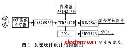
The entire system hardware design consists of power, video signal processing, FPGA and peripheral interfaces. The image processing module receives the analog video signal transmitted by the CCD image sensor, and converts the analog video signal into a digital signal, and the converted digital signal is processed by the DSP, and then converted into a standard YUV 4:2:2 format number. The video signal is sent to the FPGA module, and the YUV digital signal is processed to generate a standard SVGA format with a frame rate of 60 Hz and a field sync signal. Figure 1 is a block diagram of the hardware design of the system.
2.2 Power Module
The power module converts the externally input 12 V DC power to the required operating voltage of each module in the system. The CCD image sensor requires 15 V and -7 V, the DSP requires 3.3 V and 5 V, and the FPGA requires 1.2 V, 2.5 V, and 3.3 V. This design uses MOTOROLA's DC-DC power converter, MC34063A converts 12 V DC voltage into 5 V DC voltage, and uses Texas Instruments' power converter TPS75003 to convert 5 V DC power to 1.2 V, 2. 5 V and 3.3 V DC voltage. The operating voltage of the CCD image sensor is generated by NE555 and 78L15.
2. 3 image processing module
2.3.1 Image Acquisition
The image acquisition circuit of the design converts the analog video signal outputted by the CCD sensor into a discrete analog video signal, and then performs correlated double sampling and automatic gain control processing on the analog signal, and then transmits the signal to the DSP for conversion into a digital signal. Specific workflow: After the system power-on reset, the DSP (CXD3142) generates a control signal to drive the CCD image sensor, converts the optical signal into a PAL analog video signal, and inputs the signal to the pin DIN and PIN pins of the CXA2096N. At this time, the input signal is correlated and double-sampled under the control of the pins SHD and SHP. When the falling edge of the SHD signal comes, the DIN signal level is sampled. When the falling edge of the SHP signal comes, the pre-added level signal of the PIN pin is resampled, and the two signals are sent to the CXA2096N internal automatic gain control circuit. , output after the difference operation. The output signal is then subjected to black level clamping, pre-blanking, etc., and then output by the DRVOUT pin of the CXA2096N. The DSP generates the working timing of the CXA2096N.
2.3.2 Video Signal Processing (CXD3142R)
This design uses SONY's dedicated signal processing device CXD3142R as the signal processor. The CXD3142R is a low-power, high-efficiency signal processor designed to process Ye, Cv, Mg, and G complementary color single-chip CCD output signals. It has automatic exposure and auto white balance to simultaneously output composite video signals and YUV 8 Bit digital signal output. The internal 9-bit A/D converter synchronization signal generation circuit, external synchronization circuit and clock control circuit are integrated. In addition, the CXD3142R also has a serial communication function. The user can preset the register value in the DSP in the PC, download it to the DSP through the serial port, and perform automatic exposure and automatic white balance processing on the image signal. 2 is a circuit connection diagram of a video signal processing module.
Reel with double-skin flanges, in pressed steel with a turned drum. The external flange curl is suited for lifting through automatic hooks. The available sizes are as per DIN 46395 / 46397 specifications or as indicated by the Customer, for a normal use up to 1250 mm of flange diameter. This reel is dynamically balanced for speeds up to 60 m/s.
Indicated for metallic wires and cables.
To be used on a wiredrawing, stranding or rope-making machine. It withstands annealing treatment
| Serial Number | Specification Model | Lateral Plate Diameter D1 | Major Diameter D2 | Axle Hole Diameter D4 | Carrying Hole Diameter D5 | Center Distance E of Axle Hole and Carrying Hole | External Width L1 | Internal Width L2 |
| 1 | 400 | 400 |
224/250 280 |
125/127 | 28 | 100 |
265 300 |
224 250 |
| 2 | 500 | 500 |
280/315 355 |
125/127 | 28 | 100 |
300 375 |
250 315 |
| 3 | 560 | 560 |
315/355 400 |
125/127 | 28 | 100 |
355 425 |
280 355 |
| 4 | 630 | 630 |
355/400 450 |
125/127 | 28 | 100 |
375 475 |
315 400 |
| 5 | 710 | 710 |
400/450 500 |
250 | 40 | 170 |
425 530 |
355 450 |
| 6 | 800 | 800 |
450/500 560 |
250 | 40 | 170 |
475 600 |
400 500 |
| 7 | 1000 | 1000 |
560/630 710 |
250 | 50 | 250 | 750 | 630 |
| 8 | 1250 | 1250 |
710/800 900 |
250 | 50 | 250 | 950 | 800 |

Double Layer Wire Spools, Cable Spool, Steel Cable Reel,Steel Wire Drum
NINGBO BEILUN TIAOYUE MACHINE CO., LTD. , https://www.spool-manufacturer.com