1 Introduction
In recent years, LED light sources have required LED drivers to support an increasingly wide output voltage range (eg 25%-100%) and output current range (eg 1% to 100%, or even 0.1%-100%) to achieve a wider range. Dimming range. In order to improve the versatility of the LED driving power supply, it is required to use the same driving power source to support different LED light sources. At the same time, the circuit is required to be simple, low-cost, high-efficiency, high-reliability, and long-life.
The ICL5101 with 16-pin package, integrated PFC and half-bridge resonant controller, and the LCC topology is a good target for achieving the above goals. Its high integration reduces the number of external components and is ideally suited to combine the advantages of LCC high performance. It achieves an extremely wide output voltage and current range (voltage 25%-100%, current 0-100%), and full load efficiency exceeds 93%, while the circuit is simple and low cost. Due to the nature of the LCC, it can also achieve constant current without secondary current feedback.
2. Output range of LLC and LCC topology
In order to cope with the diversity of the number of output lamp beads and the driving current, and to reduce the number of items of the LED driving power source, it is necessary to increase the versatility of the driving power source as much as possible, and the output voltage and current range are required to be relatively wide.
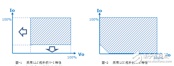
At present, the design of high-power constant-current LED driving power supply, the common soft switching topology is LLC, and its output VI characteristics are shown in Figure-1. As can be seen from the figure, the output voltage and current range lower limit of the LLC topology are relatively high. As users' requirements for dimming become higher and higher, the limitations of this output characteristic of the LLC topology are becoming more and more obvious. If the output direct current is constant, the voltage of the LLC topology at constant current cannot be very low, that is, the adaptability to the number of lamp beads is limited; when it is necessary to dim the specific lamp string with relatively fixed voltage At this time, the dimming current cannot reach a relatively low range in a relatively narrow frequency range. If deep dimming depth is required, intermittent work is often required to achieve a small average current, even with an additional level of DC/DC current, resulting in additional ripple current or increased system cost and reduced efficiency.
A more advantageous topological LCC is proposed to reduce the lower limit of the output voltage and current over a relatively narrow frequency range, as indicated by the arrows in Figure-1. After the reduction, the range shown in Figure-2 will be reached, and the lower limit of the output voltage and current can reach almost zero, which greatly improves the adaptability of the driving power supply.
3. LLC and LCC topology and some output characteristics
Figure 3 and Figure 5 are the topology diagrams of LLC and LCC. The LCC topology is only used to replace the inductor in parallel with the load into a capacitor. Finally, it consists of an inductor, a capacitor in series, and a capacitor connected in parallel with the load.
Figures 4 and -6 show the output current versus frequency of LLC and LCC, respectively, and the different curves represent different load resistance conditions.
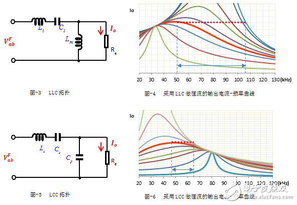
The dotted line in the two figures is the constant current trajectory. When the load resistance changes, the operating frequency needs to be changed accordingly to make the current remain stable. As can be seen from Figure 4, when the constant current output is implemented by LLC topology, different loads The spacing between the lines is large, meaning that the frequency varies greatly. As can be seen from Figure -6, when the constant current output is realized by the LCC topology, the interval between different load lines is relatively tight, which means that the frequency variation is small. That is to say, when the LCC topology implements constant current, the range of frequency variation with load is much smaller than that of LLC.
A similar analysis can be done. When dimming is applied when the output voltage is fixed, the LCC can also achieve a smaller frequency variation range than the LLC, and the current adjustment depth is deeper.
In addition, the performance of the output short circuit is also a very important indicator for the driving power supply. For the LLC topology, when the load resistance is reduced to short circuit, because it is connected in parallel with Lm, the inductive part of the resonant cavity impedance will be weakened, and the capacitance will be It will be enhanced and easy to enter the capacitive area, resulting in a switch that is prone to hard switching (when the minimum operating frequency is less than the resonant frequency). For the LCC topology, when the load resistance is reduced to a short circuit, because it is connected in parallel with Cp, the capacitive portion of the resonant cavity impedance will be weakened, the inductivity will be enhanced, and the circuit will still operate in a safe inductive region. The minimum operating frequency of the LCC is designed to be greater than (even much greater than) the resonant frequency of the series and series capacitors to ensure that the circuit operates in the inductive zone to achieve ZVS. When the output is shorted, the frequency is reduced, but is limited to the minimum operating frequency. By properly designing the resonant cavity, the short-circuit current can be made slightly larger than the rated output current, such as 110%-120%.
It can be seen from Figure -6 that there is a certain frequency point, which is the resonant frequency when the resonant inductor and the two capacitors are connected in series. When the load resistance changes, the current will converge at a fixed point. Note If the circuit is operating at this frequency, the output current naturally achieves constant current without current sampling as feedback. With this feature, the current sampling and feedback circuit can be omitted, making the overall circuit more cost-competitive, and even competing with the "PFC + flyback" topology, making its competitive power application range wider, as small as 30W. , up to 300W.
A GFCI outlet receptacle is different from conventional receptacles.
In the event of a groud fault, a GFCI will trip and quickly stop the flow of electricity to prevent serious injury.
How does LED Trip indicators work?
Indicator: 2 LED Trip Indicators (Red & Green)
• Red-The device needs attention. the device is engineered to conduct a self-test internally every 2 minutes to ensure the protection is on. If the device fails the test, the red light is on to signal that the device should be replaced
• Green-The device has passed self-test and working properly
Regular GFCI UL,Receptacle GFCI,GFCI Outlet with UL943,GFCI Receptacle
Hoojet Electric Appliance Co.,Ltd , https://www.hoojetgfci.com