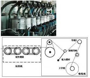
The picture above shows a simple drawing of a small wire drawing machine. From the mechanical point of view, it can be decomposed into a drawing part and a take-up part. From the electrical control, it can be decomposed into a wire drawing stepless speed control and a constant tension tension control of winding. Position change, feedback control system, after automatic calculation, change the winding motor operating speed, so as to achieve the constant tension and speed synchronization in the winding and drawing two links, and through the cable guide roller motor, with the winding speed Differently, the finished metal wire is evenly wound on the take-up reel so as to realize the stretching processing of the metal material.
The control mode of the small wire drawing machine shown in the figure above is the current mainstream control method. The stretching and take-up control is completed by the PLC or the IPC of the IPC. The frequency converter receives the PLC or IPC instructions and realizes the stepless stretching. Constant tension control for speed regulation and take-up. This system solution will directly lead to high costs, complex systems, difficult maintenance, high maintenance costs and poor system control response.
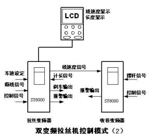
Number of recommended programs
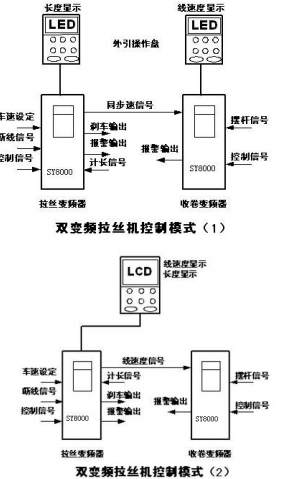
The above schematic diagram is the control method recommended by Nunn to you. The two medium, small, and miniature wire stretcher electrical control methods integrate the functions of synchronization and tension control, system startup and stop control, and fault alarming in the inverter. , Integrate with the mechanical system, the external signal is directly sent to the inverter, the internal algorithm quickly responds to the direct control of the system, greatly improving the system's response speed, eliminating the PLC, HMI, IPC, saving system cost, reduce Fault point, and can be configured according to user needs LED or LCD operating panel, reflecting the humane operation of the human machine, user-friendly operation, maintenance, commissioning and use.
Product introduction: SY8000-L special inverter
SY8000-L special-purpose frequency converter is based on the hardware platform and core control algorithm of SY8000-G high-performance vector frequency converter, combined with the requirements of dual frequency conversion medium, small and mini wire drawing machines, developed a special double Inverter of variable-frequency control wire drawing machine, in order to meet the requirements of industrial applications, has done a lot of special treatment in hardware, software algorithms, structure, especially for high temperature, anti metal dust, anti-humid, anti-corrosion treatment, greatly enhanced Frequency converter in the wire drawing machine industry reliability.
1, current vector control
SY8000-L dedicated inverter uses ARM (32-bit) + DSP (16-bit) dual CPU control system, the function control and performance control are completely separated, the underlying high-performance motor control module uses current vector control algorithm, that is, the stator current according to the coordinates The change is decomposed into an excitation current component and a torque current component, and the respective controls are performed so that high-precision control of the torque can be achieved.
Advantages of vector control compared to V/F control
(1) Excellent low frequency torque characteristics
(2) Dynamic response characteristics are good and can quickly respond to changes in load
(3) High speed control accuracy and high precision synchronous control
(4) Direct torque control, high precision without feedback torque control without PG, low cost tension control
2, the main technology
3, peripheral configuration
4, security self-test function
5, super protection
6, the standard manufacturing platform
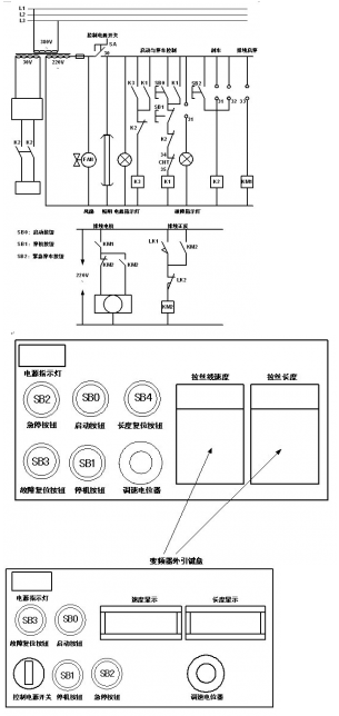
System electrical control introduction:
1, the inverter without digital display function electrical control diagram
2. Inverter with digital display control electrical control diagram
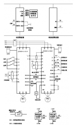
3, when using precautions
1) Wire drawing host:
(1) Input the frequency converter from the 4 analog input ports through the potentiometer and set the drawing speed. Users can set different drawing speeds according to different materials. The operation is simple and convenient;
(2) Control start, jog threading, fault reset, emergency stop, break fault input and other functions through the switch terminals;,,,,
(3) From HDI1 and COM, input the pulse length signal, the system automatically converts the drawing length, and completes the fixed length control and the processing of the length display of the wire;
(4) The actual operating frequency of the host computer is output to the coiling frequency converter through 2 ports (0~10V), as synchronous speed setting and drawing line speed display;
(5) Provide +24V, COM to external control system;
(6) Relay RO1 is a broken fault alarm output;
(7) Relay RO2 is the low-frequency brake output when the system is decelerated and parked to achieve low speed braking of the take-up motor;
(8) The host external operating panel shows the length of drawing, the unit is 0.01km, and the range is 0.01~650.00km;
2) Take-up motor
(1) Analog 4 is synchronous speed input (0~10V);
(2) Analog 5 is the tension pendulum position detection signal input port, which is used as the PID feedback path to realize the pre-PID synchronous control. The stable operation position of the pendulum rod is determined by the PID given value, usually setting P9.01 to 50. % to ensure that the swing rod is in the middle position;
(3) Control start, coil diameter reset, fault reset, emergency stop and other functions through the switch terminal;
(4) The braking resistor is required for rewinding the inverter. For the SY8000-L special inverter, the power is less than 15KW. The built-in braking unit is standard, 18.5KW or more, and the external braking unit is optional. For the specific requirements of the braking resistor configuration, please refer to the "Product Specification";
(5) Relay RO1 is a broken fault alarm output;
(6) Relay RO2 adopts FDT frequency detection function to control start and stop of cable motor
(7) The winding external drawing operation panel displays the drawing line speed in units of 0.1M/Min and the range is 0.1~6500.0 M/Min. The user can set the line speed display coefficient PA.14 to achieve accurate line speed and rotation speed. Correspondence;
In addition: Note that all signal cables in the electrical control system need to use shielded cables. The shield network must be reliably connected to the earth (PE terminal), and the strong and weak currents must be separated to avoid line-to-line interference. Other control requirements should be adjusted according to the actual situation of the customer system to meet customer needs.
4, reliability design
1, a full range of independent air duct design
2, wide network voltage design
3, 18.5kW ~ 90kW standard equipped with DC reactor