When designing more complex PCBs, it's essential to make several design trade-offs. These decisions can significantly impact the power distribution network (PDN) of the board. One critical factor is the inductance introduced by the placement of decoupling capacitors.
Once a capacitor is mounted on the PCB, an additional loop inductance is created, which depends on how the capacitor is placed. The magnitude of this inductance varies based on the layout and physical dimensions of the traces connecting the capacitor to the via. Factors such as trace width, length, via spacing, hole diameter, and pad size all play a role in determining the overall loop inductance. Figure 1 illustrates different mounting patterns for capacitors on a PCB.
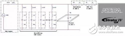
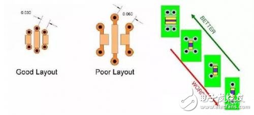
Figure 1: Best and worst capacitor layouts
Key Design Tips to Minimize Capacitor Loop Inductance:
â– Place vias as close as possible to the capacitor. Reduce the distance between power and ground vias. If possible, use multiple pairs of power/ground vias in parallel. For opposite polarity currents, place the vias as close together as possible, while keeping same-polarity vias further apart.
â– Use short and wide traces to connect the capacitor to the vias. This helps reduce inductance and improves high-frequency performance.
â– Mount capacitors on the top or bottom layer of the PCB, as close as possible to their respective power and ground planes. This reduces the distance between the capacitor and the plane, thereby minimizing loop inductance. Using thin dielectric layers between power and ground planes also helps lower inductance.
Next, we’ll explore three different scenarios for capacitor placement and signal propagation. Figure 2 shows the loop inductance values for each of these cases, highlighting how layout choices affect PDN performance.
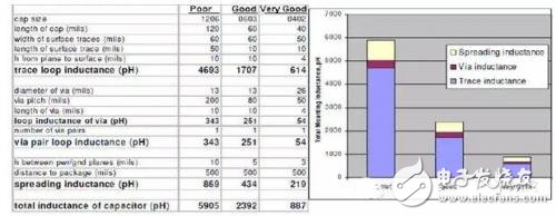
Figure 2: Different design scenarios
A siren is a loud noise-making device. Civil defense sirens are mounted in fixed locations and used to warn of natural disasters or attacks. Sirens are used on emergency service vehicles such as ambulances, police cars, and fire trucks. There are two general types: pneumatic and electronic.
Many fire sirens (used for calling the volunteer fire fighters) serve double duty as tornado or civil defense sirens, alerting an entire community of impending danger. Most fire
sirens are either mounted on the roof of a fire station or on a pole
next to the fire station. Fire sirens can also be mounted on or near
government buildings, on tall structures such as water towers,
as well as in systems where several sirens are distributed around a
town for better sound coverage. Most fire sirens are single tone and
mechanically driven by electric motors with a rotor attached to the
shaft. Some newer sirens are electronically driven speakers.
Fire sirens are often called "fire whistles", "fire alarms", or
"fire horns". Although there is no standard signaling of fire sirens,
some utilize codes to inform firefighters of the location of the fire.
Civil defense sirens also used as fire sirens often can produce an
alternating "hi-lo" signal (similar to emergency vehicles in many
European countries) as the fire signal, or a slow wail (typically 3x) as
to not confuse the public with the standard civil defense signals of
alert (steady tone) and attack (fast wavering tone). Fire sirens are
often tested once a day at noon and are also called "noon sirens" or
"noon whistles".
The first emergency vehicles relied on a bell. Then in the 70s,
they switched to a duotone airhorn. Then in the 80s, that was overtaken
by an electronic wail.
Piezo Alarm,Siren And Alarm,Piezo Buzzer Siren,Piezo Buzzer Alarm Siren
Jiangsu Huawha Electronices Co.,Ltd , https://www.hnbuzzer.com