This article describes an FPGA-based digital cipher lock. Using a top-down digital system design method, the digital code lock system is decomposed into several subsystems, and further divided into several modules, and then these modules are designed with the hardware description language VHDL, and hardware tests are performed at the same time. The test result shows that the digital code lock can verify the 10-digit decimal number password, and can preset the password, and has the functions of power-off protection device, decoding effective indication and the like.
1 Feature Overview
(1) The working clock of the combination lock is provided by an external crystal oscillator. The clock frequency is 50MHz, the operation speed is high, and the working performance is stable.
(2) The setting and input of the password are completed by an external keyboard, and the control circuit has high safety factor and convenient operation;
(3) The password number can be set freely by the owner of the lock and can be changed to enhance the user experience. The password modification must comply with the preset rules, otherwise the password cannot be modified.
(4) When unlocking, the number of input digits of the password is not limited (1 to 10 digits are available), which reduces the probability that the password is cracked (about one billionth of a crack rate), and the password lock has high confidentiality.
(5) Clear the password key setting, you can quickly clear all passwords, and improve the ability to adapt to emergencies.
(6) The input digital password can be directly displayed, and can be converted into an asterisk to prevent voyeurism and enhance confidentiality.
(7) After all passwords are entered, the password lock will be activated when correct, and the display will appear: Input Right! The indicator light is on. When the error occurs, the display shows: Input Failed! The indicator light goes out.
(8) A power-off protection device is provided to ensure that the circuit does not lose the modified password due to power failure, and returns to the original password value to enhance the stability of the password.
2 system structure
The system design mainly includes hardware design and software design, both of which adopt modular design. The hardware design mainly includes the central control module, the microcontroller, the display module, the input module, and the peripheral circuit. The software design includes a state control module, a logic control module, a liquid crystal display driver module, an EPROM drive module, and a scan input module. The system structure framework is shown in Figure 1.
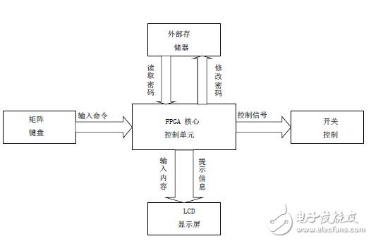
Figure 1: System structure framework
The design adopts modular programming. The whole program consists of LCD LCD 1602 module (LCD1602.v), matrix keyboard module (Matrix_Keys.v), memory chip AT24C02 module (AT24C_XX.v) and top logic function module (password.v). The top-level logic function module (password.v) calls the other 3 modules to complete the design of the top-level functions. as shown in picture 2.
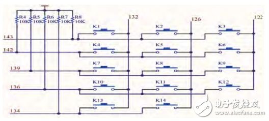
Figure 2: Matrix Keyboard Schematic
3 bottom design
3.1 Input module
Due to the large number of keyboard buttons, in order to reduce the occupation of the I/O port, the design arranges the buttons in a matrix form. In a matrix keyboard, each horizontal line and vertical line are not directly connected at the intersection, but are connected by a button. In this way, 8 ports can form 3*5=15 buttons. In fact, we only need 14 buttons to solve the password problem, which is more than double the port line for the keyboard, and the number of lines is more. The more obvious the difference, for example, adding one more line can form a 20-key keyboard, and directly using the port line can only have one more key (9 keys). Therefore, when the number of keys required is relatively large, it is more reasonable to use the matrix method to make the keyboard.
3.2 display module and peripheral circuits
This design selects LCD1602 as the core of the display module, which can conveniently display the required numbers and prompts, and has the advantages of user-friendly interface, low power consumption, fast speed, and saving Controller resources. The peripheral circuit is mainly an LED controlled by the controller, indicating that the lock is turned on and off.
3.3 storage module
This design uses the memory chip AT24C02 as the external memory for the password. Two-wire serial EEPROM—24C02 is a low-voltage 2K-bit serial EEPROM with an internal organization of 256 bytes and 8 bits per byte. The chip is widely used for low voltage and low power. Consumption of industrial and commercial areas. The design uses the I2C protocol to connect the controller to the memory, save the password, and ensure that the password is not lost due to power failure.
4 working methods
The system uses the above system modules as the hardware foundation, and uses VHDL language to write programs, which realizes five main functions:
(1) Confirm password: By scanning the matrix keyboard, judging the user input content, comparing the typed number with the password in the password memory, judging the correctness of the password, and controlling the switch of the password lock;
(2) Clear password: If a key error occurs during the input of the password, you can clear all current passwords by selecting the clear key to facilitate re-entry;
(3) Password protection: The display mode can be switched by displaying the switch key. In the display digital mode, the display shows the input number, which is convenient for the user to operate; in the protection mode, the displayed password is indicated by “*†to prevent external voyeurism and improve safety performance;
(4) Change password: When the password lock is open, the current user is recognized as the holder of the lock by default, and the password is allowed to be modified. However, the password must be changed to meet the "potential rules" set in the password lock. Otherwise, the modification cannot be completed to prevent the password lock from being destroyed.
(5) Power-off protection: Set the circuit protection structure to ensure that the circuit will not lose the modified password due to power failure, and return to the original password value.
Its work flow chart is shown in Figure 3.
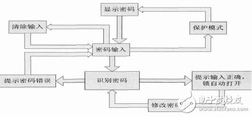
Figure 3: Work flow chart
5 Simulation and debugging
In the design process, first simulate each module, use software such as Quartus II, and then program the program for hardware debugging. Finally, the entire system program is fully compiled, and the software simulation of the entire system is performed. After the simulation is passed, the hardware tuning of the entire system is performed.
6 core features
This design pioneered the concept of modifying the password "potential rules". When the password is changed, the new password must meet the potential rules preset when the password lock is created. Otherwise, the password cannot be successfully modified. For example, the password must be Seven-digit number, if you enter a five-digit number when changing the password, the password modification will fail. The significance of this design is that when the intruder obtains the correct password and unlocks it by illegal means, if the potential rule cannot be found within a short period of time, the password must be discarded to prevent the user's interest from being damaged twice. In addition, the design of the underlying rules can also be all the digits of the password and equal to N, must be even, etc. Each of the potential rules has a corresponding specification, so even if mass production does not have the problem that the potential rules are cracked. In addition, when the user forgets the password, he can contact the potential rule recall password according to the manual. In addition, the password lock supports 1~10 digits of any digits as a password, which is much larger than the general password lock. It is extremely flexible and can be combined with about 1.1 billion password combinations. Probably, the random crack password is not Possible event.
7 Conclusion
Based on the characteristics of FPGA for design state machine, Quartus II simulation and physical test prove that the digital code lock has the characteristics of perfect function, stable operation and high safety factor. By modifying the innovation of the password scheme, it can be used in practical applications. It further shows excellent safety performance and has a good development prospect.
Using latest technology and expertise knowledge, we are indulged in providing Monocrystalline Solar Panel. Our Monocrystalline Solar Panel is highly appreciated amongst clients for its excellent features such as reliable operation and dimensional accuracy. Clients can buy this product from us at industrial leading price.
Monocrystalline Solar Panel
Monocrystalline Solar Panel,Monocrystalline Silicon Solar Panel,High Transmission Rate Solar Panel,Photovoltaic Cell Solar Panel
Delight Eco Energy Supplies Co., Ltd. , https://www.cndelight.com