Abstract: In view of the problem that the detection of motor vehicle braking performance relies on the long detection period and poor self-detection capability caused by the mandatory inspection of the vehicle management department, the characteristics of the three-axis sensor are combined with the improved backward integration algorithm to detect the motor vehicle in real time. Brake performance information and send test data over the mobile network. The hardware composition and operation flow of the system are briefly described. The system has complete functions, low cost and convenient installation, and has good economic and social benefits.
This article refers to the address: http://
The braking system of a motor vehicle is an important guarantee for its safe operation. Whether its performance is qualified is directly related to the personal and property safety of motorists and passengers. Therefore, the state has formulated GB7258-2012 (Safety Technical Conditions for Motor Vehicle Operation) and GB12676-1999. (Automobile Brake System Structure, Performance and Test Method) provides clear test methods and technical indicators for brake system detection. Motor vehicle brake system includes service brake, parking brake and emergency brake, our daily main detection Driving brake performance. GB7258 specifies two test methods for driving performance, namely road test and bench test. The road test method is the most widely used in actual test because it is more comprehensive and closer to the actual situation. The key indicators of the road test to test the driving performance are braking distance, full deceleration (MFDD), initial braking speed and braking coordination time.
At present, the braking performance test of the whole vehicle usually uses a five-wheeled instrument or a non-contact speed measuring sensor to measure the braking distance, and the testing process is cumbersome, which is not conducive to normal monitoring. The acceleration sensor can accurately record the braking acceleration during the braking process, and the braking algorithm can be used to obtain the braking distance and other parameters. The three-axis acceleration sensor can simultaneously record the direction of travel of the motor vehicle, the horizontal direction and the longitudinal acceleration of the vehicle during braking. By processing the three-axis acceleration data, the nodding error, vibration error and the like in the braking start process can be removed. Aiming at the problem that the current braking performance detection relies on the long interval of detection interval and the poor detection ability caused by the mandatory inspection by the traffic management department, a form of networked detection is proposed. The improved braking performance detector can periodically and qualitatively detect the braking performance of the vehicle and report the detection result to the management department, and the real-time detection can be performed by the superior department to control the instrument, thereby forming a closed-loop network from detection to supervision. It greatly improves the transparency and real-time performance of vehicle safety monitoring. In passenger transport companies, units with high requirements for vehicle safety, such as dangerous goods transportation, have good social and economic benefits and have good market prospects.
1 system hardware design
1.1 Hardware structure principle
The system is mainly composed of three-axis acceleration sensor, microcontroller (MCU), pedal force sensor, 3G module, ferroelectric memory, etc. The block diagram of hardware is shown in Figure 1.
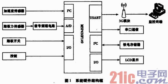
Each round of the system detects that the pedal switch is pressed as the start signal, and the AD (digital-to-analog conversion) module of the single-chip microcomputer starts to convert the analog signal input by the pedal force sensor, and at the same time, reads the acceleration data of the acceleration sensor through the I2C interface. After entering the data processing program, the whole braking process is analyzed, and the initial braking speed, braking time and braking distance of the motor vehicle during braking are calculated, and the average deceleration (MFDD) and braking coordination time are fully issued. BCT) and other parameters. And compared with the specified value, the final result of this braking performance test is obtained. After the basic data and the detection result are stored in the ferroelectric memory, the result is uploaded to the monitoring terminal through the 3G module EM770W, and the basic data can be uploaded according to the requirements of the upper computer for further analysis and processing. After receiving the host computer instruction, the instruction is stored in the memory for the next detection.
1. 2 Acceleration sensor selection and interface design
In the road test, the acceleration data is the basis for calculating the key parameters such as the initial braking speed, braking distance, and MFDD. Therefore, it is necessary to select an appropriate acceleration sensor and an appropriate algorithm. Single- or dual-axis accelerometers are commonly used in portable brake testers on the market today. Therefore, there is a strict requirement for the placement of the instrument during the test, and one direction must coincide with the direction of travel of the vehicle. This causes great inconvenience to the test, and the overall sway or jitter of the vehicle directly affects the measurement result due to the presence of a nodding error at the beginning of the braking process and a bump on the roadside. The three-axis accelerometer can be placed casually, because the calculation of the three-axis and acceleration, thereby reducing the impact of the nod error and road bumps on the test results.
1.2.1 Three-axis MEMS accelerometer selection
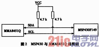
The acceleration sensor uses Freescale's MEMS three-axis digital output accelerometer MMA8451Q. The MMA8451Q features a configurable range (±2g/±4 g/±8 g), configurable resolution (14-bit, 12-bit, 10-bit) and embedded features for precise motion through the corresponding register configuration analysis. At the same time, it has a low power consumption design, and can be configured according to actual needs. It has six user-configurable data output rates ranging from 1.5 to 800 Hz, with sleep and wake-up modes, and a minimum operating current of only 6 μA. The MMA 8451Q has two programmable interrupt pins that can be used by seven interrupt sources to communicate with the controller via the I2C interface. The operating voltage is 1.95 V to 3.6 V, the interface voltage is 1.6 V to 3.6 V, and the QFN is 3 x 3 x 1 mm. Small package. Its connection to the MSP430 is shown in Figure 2.
1. 3 pedal force sensor selection and interface design
The "Safety Technical Conditions for Motor Vehicle Operation" specifies the size of the pedal force of a hydraulic brake system, and its maximum qualified pressure is 700 N. Therefore, the range of the pedal force sensor is selected to be 0 to 1 000 N. The pedal force sensor is selected from LDCZL to TL of Beijing Longding Technology. The pedal force sensor is a resistance strain gauge sensor, which can perform pressure force test and has good output symmetry. It has the characteristics of high measurement accuracy, compact structure, good stability and small temperature drift. Its volume is flat, it can be flexibly and conveniently installed on the car pedal, adopts the hole width structure, has the innate anti-stepping biasing force and small volume, strong anti-vibration ability and output voltage signal. The operating voltage is ±10 V DC and the sensitivity is 1.5 mV/V, which can meet the test accuracy requirements of the system.
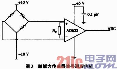
Since the pedal force sensor is mounted on the car pedal, it is close to strong interference sources such as the engine and the starting motor. And because the requirements of the driver and each test item are different, the output signal of the bridge has a wide range of variation, and the signal detection circuit is required to have low noise, low zero drift, high noise resistance, wide adjustable gain, etc., and the instrument is selected according to the above requirements. The amplifier AD623 acts as a pedal force signal amplifier. The AD623 is an integrated single-supply instrumentation amplifier that maintains minimal error by providing an excellent AC common-mode rejection ratio (AC CMRR) that increases with gain gain. Line noise and harmonics will be due to common-mode rejection ratios. It is suppressed while being constant up to 200 Hz.
It provides rail-to-rail output from a single supply (+3 V to +12 V), allowing gain programming through a gain-adjusting resistor for flexibility, with gains up to 1000 times and gain-regulated resistors The following formula is obtained:
RG=100 kΩ/(G-1)
The pedal force sensor signal conditioning circuit is shown in Figure 3.
1.4 Microcontroller Selection
In order to work in a variety of scenarios, the device uses two-way power supply, through switch selection, a routed lithium battery power supply, and a routing car internal 12 V DC direct power supply. At the same time, in order to meet the requirements of continuous monitoring, the MSP430 series MCU supporting ultra-low power consumption has four power-saving modes. The minimum operating current of LPM4 is only 0.1μA, which can be quickly switched in different working modes by internal commands. Therefore, the MSP430 series MCU has great advantages in the case of battery power supply.
The MSP430 family is a 16-bit mixed-signal processor with a rich set of on-chip peripherals, on-chip hardware multipliers, two 16-bit timers with PWM capability, and a 14-channel 12-bit analog-to-digital converter. The MSP430 provides a built-in voltage reference (2.5 V), a watchdog timer, two USART communication ports, a comparator and supports an 8 M clock. Simultaneously
The MSP430 has a rich set of I/O ports with interrupt capabilities and a large capacity of Flash and RAM.
In summary, the MSP430 has a wealth of resources to simplify the circuit design of the system, shorten development time, reduce system cost, and its low power consumption can improve the portability of the system, so it is used as a brake performance monitoring system. Device.
2 software and algorithm design
The system takes the three-axis acceleration sensor as the core. After the system is turned on, the system reads the command sent back from the host computer and the last address of the data storage after the last detection. After the pedal force sensor is depressed, the acceleration data and pedal force data are entered. During the acquisition phase, the braking process is timed by the MSP430 internal timer. At the same time as the data is collected, the data acquisition time point is recorded. After the braking process is completed, the pedal force, the average brake deceleration and other parameters during the braking process are calculated by the corresponding data processing program, and the test data is sent back to the upper computer for data analysis, graphic display and recording. The lower computer waits for the control instruction of the upper computer, and stores it in the memory after receiving the instruction. After completion, it returns to the initial value state of the pre-reading system, and thus completes a closed-loop detection and reporting.
2.1 System main program design
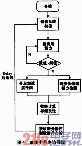
The software design adopts the modular idea. The system consists of data acquisition module, system control module and data transmission module. The system flow chart is shown in Figure 4.
2.2 Data Processing Algorithm Design
The system begins to acquire acceleration signals when the pedal force sensor detects pressure and exceeds the threshold. Since the pedal effort does not reach the maximum value at the start of braking, pedal force data is acquired at a frequency of 10 Hz with the timer switch interrupt after the start of braking. At the same time, the acceleration data is read from the acceleration sensor. The data acquisition stops after continuously collecting 10 sets of acceleration data below 0.1g, enters the data processing flow, and calculates parameters such as initial braking speed, average braking deceleration, braking distance and the like.
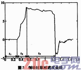
The braking process of a motor vehicle can be divided into three parts, as shown in Fig. 5, which are respectively t1: mechanical reaction time; t2: braking force increasing time; t3: braking force duration. The mechanical reaction time t1 starts from the time when the pedal force is collected to the pedaling, and continues until the braking force starts to rise. The braking force growth time t2 is the time required for the brake deceleration to rise from 0 to the stable braking phase. The end point of t2 is the starting point of the braking force duration t3. It can be seen from Fig. 5 that when the braking is completed, a negative acceleration is generated due to slight shaking of the front and rear of the vehicle, and this point is taken as the braking completion point.
During the braking process of the motor vehicle, there is a long brake preparation time from when the brake pedal is depressed to the braking effect, which brings the variables such as the initial braking speed and the braking distance during the entire braking process. Large cumulative error. Therefore, the braking key parameters are obtained by segmentation calculation, and the numerical integration is performed backward from the braking end point. The t1 phase can be regarded as a uniform motion and S1=vD·t1, and the t2 phase is a variable deceleration motion.
However, according to the actual test, the motor can also be regarded as a uniform motion during the t2 phase. Therefore, the operation S2=v0·t2 can be simplified, and the braking force continuous phase also belongs to the variable deceleration motion. At the same time, in the case of backward integration, there is a case where the error is accumulated and the sampling interval error is also caused by the sampling interval error. Large error. Therefore, the smoothing method is adopted N times, and the sampling interval Δt is substantially equal after N smoothing, so that the traveling distance and the initial speed can be directly obtained by the cumulative summation method.
2.3 PC monitoring and processing procedures
The host computer system adopts the B/S/S (Browser client browser/WebServer network server/Database Server) structure design. The lower computer sends the test data to the server in the form of message through the 3G network, and then stores it into the database through the server decoding process. At the same time, the system administrator and the motor vehicle driver can query the braking system in real time through different levels of account login webpage. When the braking performance data is at a critical value or is unqualified, the corresponding vehicle information is added to the warning window, and the management department is notified to simultaneously issue an alarm message to the driver, thereby realizing real-time monitoring and suppressing the risk factors in the initial stage.
3 Conclusion
In this paper, a vehicle braking performance monitoring system is designed. Based on the 3G network, the system uses the multi-dimensional acceleration sensor to detect the key parameters such as the average braking deceleration, braking time and braking distance during the braking process of the vehicle and via 3G. The network sends the test results to the server. In order to simplify the installation and use of the system, the high-performance and low-power processor is designed as a portable installation structure, so that the safety state of the brake system of the motor vehicle can be monitored in real time conveniently and quickly. The system has small power consumption, strong real-time performance, convenient and simple installation, strong practicability and good economic and social benefits, especially for reducing the number of traffic accidents caused by brake system failure.
Intercome speaker:
Intercome speaker is a kind of micro speaker unit which uses a diaphragm made of Mylar material. Mylar speakers are of ultrathin design and lightweight and clear voice. It is widely used in building security industry (e.g. intercom, video door phone, intelligent door control..)
There are two types of Mylar speakers from the shapes:
1) Round shapes, we have products from 10mm to 57mm in diameter.
2) Oblong shape, we have products in sizes of 1510/1712/1813-..


FAQ
Q1. What is the MOQ?
XDEC: 2000pcs for one model.
Q2. What is the delivery lead time?
XDEC: 15 days for normal orders, 10 days for urgent orders.
Q3. What are the payment methods?
XDEC: T/T, PayPal, Western Union, Money Gram.
Q4. Can you offer samples for testing?
XDEC: Yes, we offer free samples.
Q5. How soon can you send samples?
XDEC: We can send samples in 3-5 days.
Intercom Speaker,Handheld Intercom Speaker,Window Intercom Speaker,Building Intercom Speaker
Shenzhen Xuanda Electronics Co., Ltd. , https://www.xdecspeaker.com