2 System Components The 25T air-conditioned passenger car DC600V/DCI110V 8 kW charging system is composed of two parts: single unit and cabinet. Among them, the single unit has main circuit and control circuit; the cabinet part includes external incoming line terminal and input/output circuit fuse. And air switches for control, etc.
2.1 PWM high frequency bridge inverter main circuit analysis and realization DC600V/DC110V 8 kW charging system input voltage is DC600 V, power is 8 kW, adopts bridge rectifier circuit and high power DC/DC conversion circuit adapted to high voltage conversion Figure 1 is a circuit schematic diagram of the system PWM high frequency bridge DC/DC converter. The entire system consists of input isolation, filtering and buffering circuitry. The inverter bridge is composed of 4 IGBTs, the high-frequency transformer transmits power, and the transformer output is rectified and filtered by high frequency to supply DC load and battery. Figure 2 is the control logic of the main circuit of DC/DC conversion composed of V1-V4 and the logic waveform diagram of the original secondary voltage of the transformer: in the interval t1-t2, V1 and V4 are turned on, and the primary voltage of the transformer is the positive phase voltage; t3 In the interval t~4, V2 and V3 are turned on, and the primary voltage of the transformer is the reverse voltage.
This article refers to the address: http://
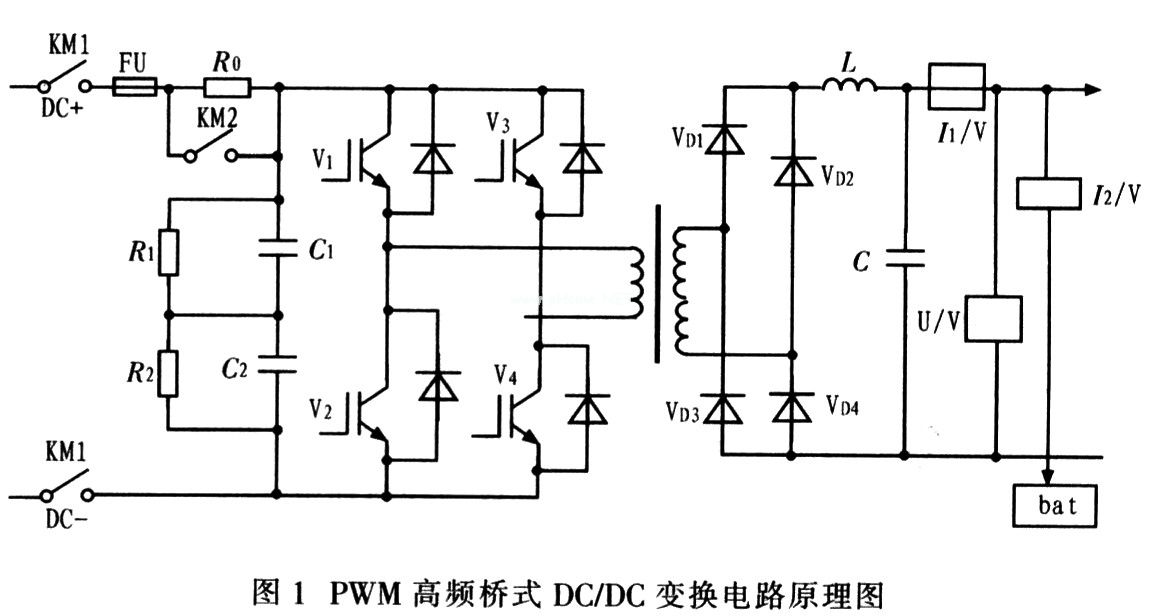
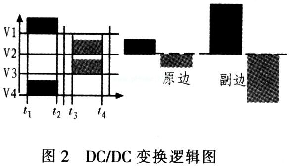
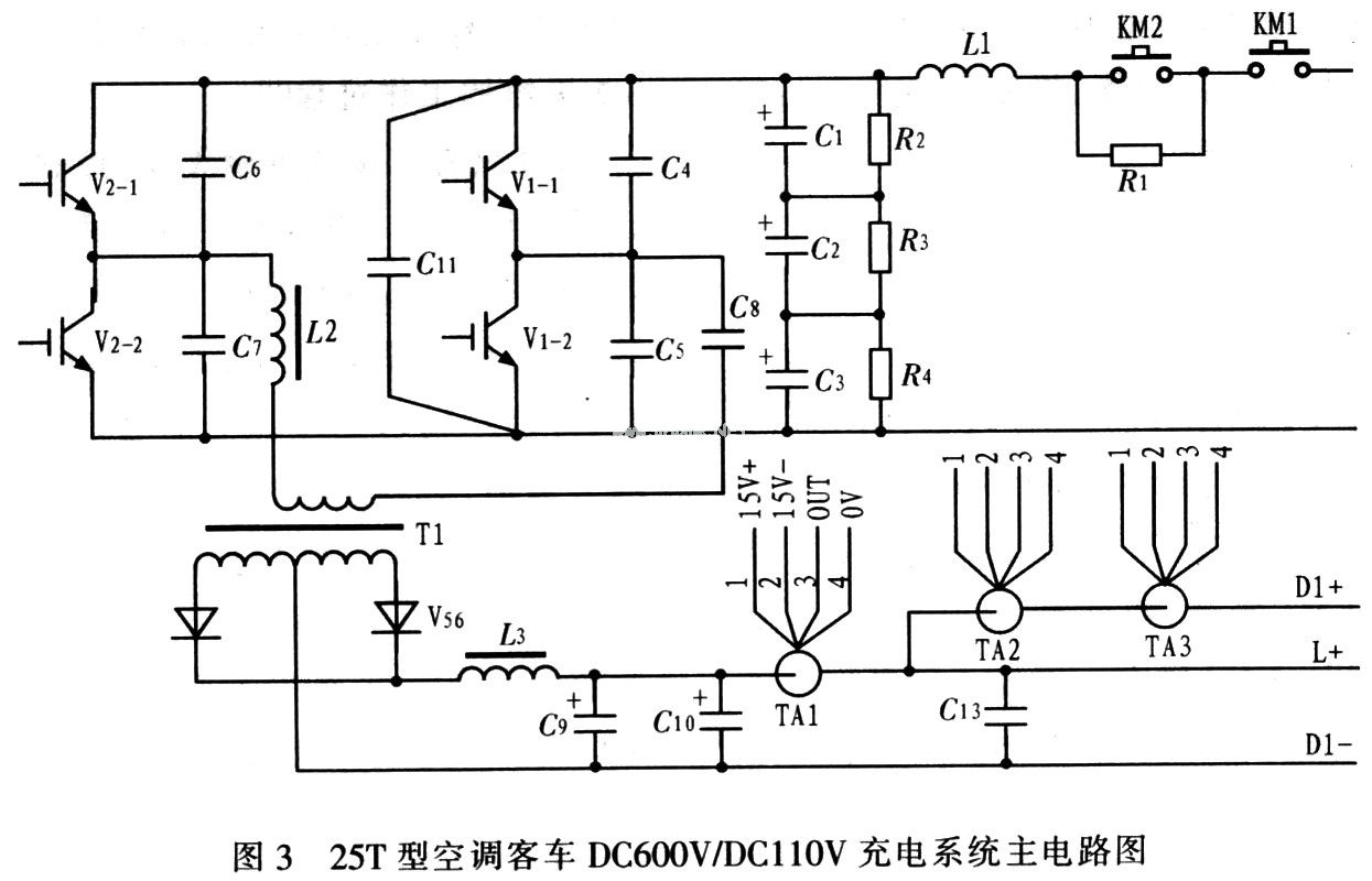
Figure 3 shows the main circuit of the DC600V/DC110V charging system for the 25T air-conditioned passenger car. Analysis of Figures 2 and 3 shows that the primary isolated DC capacitor C8 and the inductor L2 of the high-frequency transformer of the switching element IGBT power module (V1, V2) are connected to the diagonal of the bridge. The transformer is connected to the full-wave rectifier (V56) and the filters L3, C9, and C10 output 119 to 123 V DC. The main control circuit uses a phase shift control integrated circuit. The UC3875 (UC2875) is a control device that outputs two sets of (A-B, C-D) 180° complementary and hysteretic, time-adjustable IGBT gate trigger signals. Further analysis shows that all IGBTs are not turned on in the interval from t2 to t3. This period of time is called “dead zone†to prevent the two IGBTs of the upper and lower arms from being turned on at the same time, causing the bridge arm to “through†short circuit.
In the design of the system, the IGBT for the charger is generally dual-cell, that is, two IGBTs are integrated in the upper and lower arms of one module. Although the circuit structure is simple, the switching loss is usually due to the high frequency of the IGBT, which is generally around 20 kHz. Large, difficult to dissipate heat. In order to solve the problem of high frequency switching loss, the system uses phase shift technology to realize the quasi-soft switching control of IGBT. The phase shift soft switching circuit has the advantages of constant operating frequency, simple control, high efficiency, and low interference. Principle of phase shift control: Using the leakage inductance of the transformer and the capacitance resonance between the IGBT junctions, the leakage inductance LK energy storage is released to the capacitor C, so that the voltage of the capacitor C is gradually decreased to 0, and the diode VD is turned on to create a zero voltage switch (ZVS). Conditions, other inductive and capacitive components in the circuit are set to obtain a reliable zero voltage switch. The upper and lower two switching tubes (V1 and V2, V3 and V4) of the two left and right arms of the bridge are applied with 180° complementary driving signals, and the upper and lower tubes are 180° complementarily turned on. In addition to the dead zone where the upper and lower tubes are turned on, there are always two switching tubes in the circuit that are turned on at the same time. There are four kinds of conduction combinations, namely V1 and V4, V4 and V2, V2 and V3, V3 and V1, and press The order is repeated. Where V1 and V4, V2 and V3 are turned on (ie, diagonally conducting), the full bridge circuit gives energy, and V3 and V1, V4 and V2 are combined to conduct (ie, the upper arm or the lower arm) When the two tubes are simultaneously turned on, the full bridge circuit is in a freewheeling state and does not output energy. By adjusting the time ratio of the two combinations, that is, the phase shift angle, the transformer obtains an alternating PWM voltage to adjust the output voltage and current.
2.2 DC/DC conversion function and characteristics In order to reduce the size of the charger and prevent high voltage from entering the low voltage system, the system uses a high frequency insulated DC/DC converter, Figure 4 is its circuit diagram.
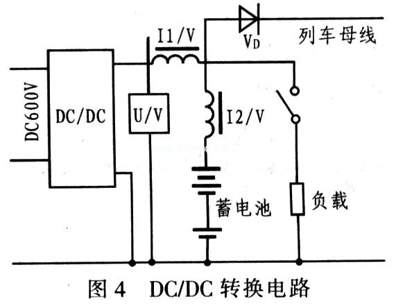
The DC/DC charger is used to convert the input DC 600 V into a DC110V suitable for battery charging and DC load use, and to stabilize the output when the input voltage and load change. The input protection and working principle of the DC/DC charger is the same as that of the inverter. The DC600V voltage is converted into a high-frequency square wave voltage with adjustable duty cycle through the IGBT bridge inverter circuit. The duty ratio refers to the ratio of the pulse width of the driving IGBT to the entire half-wave period in one half wave. In order to adjust the output voltage, the duty cycle is variable and belongs to the pulse width adjustable mode, ie PWM mode.
In this control mode, the amplitude of the pulse does not change. When the load changes, the output voltage is stabilized by changing the width of the pulse. If the input voltage changes, the output can be stabilized by changing the pulse width. After isolation by transformer, it is rectified and filtered into DC 110 V voltage. For some compatible 25T railway passenger cars, the AC 380 V is first rectified into DC 540 V, and then the same DC/DC conversion as DC 600 V is adopted. The rectifier circuit composed of 4 high-frequency fast diodes of VD1 to VD4 rectifies the pulse voltage outputted from the secondary side of the transformer, and is filtered by the reactor L and the capacitor C.
Since high-frequency rectification requires a small on-state voltage drop to reduce conduction loss, it also requires fast turn-on and turn-off capability to reduce switching losses because the diode is turned on under high frequency conditions. The losses caused by the reverse recovery time account for a significant proportion of the total loss.
DCfDC conversion features: voltage and current double closed-loop control to achieve constant current constant voltage charging of the battery; soft switching technology to reduce IGBT high-frequency switching loss, efficiency of 92%; using advanced amorphous core to manufacture transformers and reactors, Reduce the charger volume; IGBT switching frequency of more than 20 kHz, avoid the audio area, reduce the electromagnetic noise of the charger; battery charging uses temperature compensation measures; charger has fault diagnosis and communication functions, control cabinet touch screen can display charging Operating parameters and fault information.
3 system working process
3.1 Basic working principle example Figure 5 is the input circuit schematic diagram of the charging system. Working process: DC 600 V input +610 V, -610 V, through the fuse, contactor KM1, KM2, charging resistor R1, input filter inductor L1, input filter capacitor C1, C2, C3 into the charger. When the bus voltage reaches 500 V, KM1 pulls in and charges capacitors C1, C2 and C3 through R1. When the voltage on the capacitor is full, KM2 pulls in, and LC is input through input filter inductor L1 and input filter capacitors C1, C2 and C3. After filtering, a smoother DC voltage is obtained, and then DC 600 V/DC 110 V is sent to the DC link for conversion. R1 and KM2 form a soft-start circuit. When the input power supply suddenly increases, in order to avoid direct charging of the input filter capacitors C1, C2, C3, the DC 600 V input must be limited by the metal film resistor R1. When the input capacitor is full, the control contact KM2 pulls in and then changes normally. When the charger fails, disconnect KM1 to disconnect the charger and DC 600 V input.

In order to reduce the impact of the start-up work of the charger, the drive pulse of the charger IGBT also adopts a soft start mode at the start, that is, the pulse width is gradually increased, the output voltage is gradually increased, and when it rises to a certain value, voltage feedback or current feedback kick in.
The system has a current limiting constant voltage charging function. Since the 25T type passenger car adopts an alkaline medium rate battery, the requirement of alkaline battery charging should conform to the Markov curve, that is, the battery adopts a constant current charging mode when the voltage is low, when the voltage is charged to a certain extent. Take a constant pressure floating charge method. According to the unified requirements of the Ministry of Railways, the current-limiting charging value is (1+10%) × 25 A, the 25T bus battery is 120 A h, and the 5 h discharge current is 24 A, so the constant current charging current is limited to (1+10). %) × 25 A, the termination voltage of the alkaline medium rate battery float is 1.5 V, the 25T bus battery has a total of 80 knots, and the charging voltage should be 120 V, taking into account the upper limit of the voltage of most low voltage electrical coils ( 1+10%) × 110 V, which is 121 V, so the charging voltage may be low. In the application, the battery can be reduced by 1 to 2 cells.
The output current of the charger is divided into three parts, one part is charged to the vehicle battery, the other part is supplied to the vehicle lighting, control and other loads, and a part is supplied to the train bus through the diode.
The current sensor I1/V is a sensor that measures the total current output of the charger. When the output current of the charger exceeds its allowable current of 70 A, the driving pulse of the control IGBT is narrowed, the output voltage is lowered, and the charger does not decrease after the output voltage is lowered. Output current to other passenger cars while reducing battery current and reducing total output current. Since the full array of batteries and chargers are connected in parallel by diodes, the output voltage of each passenger car charger should be as consistent as possible.
3.2 System working process The system can only work normally if the wiring is accurate, the control power is normal, and the DC 600 V power supply is normal. After the system is powered on, the system starts to detect each state. If only the control power is turned on, when there is no DC 600 V input, the power system will cyclically detect and display the battery voltage and its discharge current, and indicate the input voltage and battery voltage status (undervoltage or normal), and communicate with the gateway at the same time. The corresponding information is transmitted to the PLC; if the control power supply and the input power supply voltage are DC 600 V, the converter starts to work, and the monitoring system simultaneously detects and displays the output voltage, load current, charging current and converter working state of the power system. At the same time, it communicates with the gateway and transmits the corresponding information to the PLC.
3.3 Basic protection function of the system In order to make the system work efficiently, the system is designed to input undervoltage protection, output overload protection, input spike overvoltage protection, output overcurrent and short circuit protection, input mean overvoltage protection, and output undervoltage protection. , Output peak over-voltage protection, radiator over-temperature protection, output mean over-voltage protection and power switch tube over-current protection and other protection circuits. In addition, before installing or replacing the battery, the system should first confirm that the polarity is correct and then wire.
4 Conclusion Compared with the traditional power supply of the same power, the system has the following characteristics: small size, light weight, high efficiency, high reliability, high power supply to the load: easy to use and maintain; input and output LC filter circuit and Soft start, low interference to the power supply grid, small output voltage ripple, and strong anti-interference ability. The charging system has reached the domestic advanced level.
Braided Displayport Cable,Stainless Steel Braided Cable,2 Core Braided Cable,Braided Shield Cable
Zhejiang Wanma Tianyi Communication Wire & Cable Co., Ltd. , https://www.zjwmty.com