1 Introduction Computer and communication technology has become a core part of most solutions in the industrial environment, and its proportion in the system is rapidly increasing. In an automation system, the AC and DC governors are not only a single actuator, but as they continue to be intelligent, they can be combined into one by various communication methods with each other and with the control system. Organic whole. Siemens inverter USS free port communication has been widely used in automation systems due to its high communication quality and low cost. In this paper, the practical application of USS free port communication in the electric drive system of oil drilling rig is taken as an example. The address allocation of the free port and the realization of the communication program are analyzed in detail. This idea is not only used for plc to ensure the communication quality. High-level language has certain reference significance in the preparation of communication programs implemented by PC and improving the reliability of communication.
2 USS communication
2.1 USS Overview The USS communication protocol used by Siemens AC and DC converters is a communication protocol developed by Siemens for the transmission system. It can support the communication connection between AC and DC drives and PC or PLC, and is suitable for smaller automation systems. Has the following characteristics:
(1) Solve automation problems with a single, fully integrated system. All Siemens AC and DC drives can use the USS protocol as the communication link. The original drivers are isolated and only a small amount of feedback signals are sent through the hardware circuit.
(2) Digital information transmission improves the automation level and reliability of the system, and solves the interference and drift caused by analog signal transmission.
(3) The communication medium adopts RS-485 shielded twisted pair cable, which can be up to 1000m, so the number of control cables can be effectively reduced. In the original system, 20 core control cables are generally required to be more than 4, and now only work power supply That's it, which can greatly reduce development and engineering costs and increase reliability.
(4) The communication rate is high, up to 187.5 kbps. For a system with 5 inverters, each of which has six process data to be refreshed, the typical scan cycle of the PLC is several hundred milliseconds.
(5) It adopts an operation mode similar to PROFIBUS, and the bus structure is a single master station and master-slave access mode. The message structure has parameter data and process data. The former is used to change the parameters of the governor, and the latter is used to quickly refresh the process data of the governor, such as start stop, logic lock, speed reference, torque reference and so on. Extremely fast and reliable.
2.2 Siemens USS Communication Protocol
(1) Protocol Overview â— The USS protocol defined by the Siemens driver is a simplification of the Profibus communication protocol. It can connect 31 nodes through its bus, and the transmission rate can reach 19.2k bit rate, which is controlled by the master station (PC, PLC).
• Each transmission on the USS bus has a station number through which the primary station identifies each transmission.
â— The USS can be a master-slave structure: the slave responds to the message sent by the master station and sends a message. It can also be a broadcast communication method: the message is sent to all the transmissions at the same time.
(2) Protocol Description All data messages consist of 14 bytes. It is a standard asynchronous message format: 1 start bit, 8 data bits, one even parity bit and one stop bit. The structure of the data message is as follows:
Message format from master to slave:
![]()
Message format from the station to the master:
![]()
(3) USS protocol message description â— STX STX is a single-byte ASCII STX character (value is 02) indicating the start of the message.
â— LGE LAE is a single-byte area that indicates the number of bytes after the LAE area in the packet.
â— ADR ADR is a single-byte area containing the address of the slave drive::

Bit 5 is the broadcast bit. Select whether to broadcast this message to all the drives on the bus. Bits 0~4 are the drive bus addresses.
â— BCC BCC is a single-byte area that performs XOR check on all previous bytes in the packet.
â— IND IND is a 16-bit area and the universal drive should be set to zero.
â— PKE PKE is a 16-bit area used to control the parameter reading and writing of the transmission. It is defined as follows: Bits 0~10 are parameter numbers, bits 12~15 are parameter read/write controls, such as 2038H, 2 stands for read parameters, and 38H means The parameter with a decimal ID of 56.
â— VAL VAL is a 16-bit area. The parameter value is written to the corresponding parameter ID by reading and writing the parameter command.
The STW is a 16-bit control word area that controls the operation of the transmission, such as the 047F meter to control the forward operation of the motor.
The ZSW is a 16-bit status word area that indicates the different operating states of the transmission.
â—HSW/HIW HSW is a 16-bit area for setting the motor speed. For example, 4000H corresponds to 100% of the rated speed.
The HIW is a 16-bit area that reads the motor speed and can read the motor speed. For example, current speed = (HIW × rated speed) / 4000H.
3 free port settings
3.1 Drilling Machine Transmission System Equipment Configuration For many years, China's drilling rig market has been dominated by mechanical drilling rigs. The diesel generators drive the gearboxes to adjust the speed of the winches and mud pumps. The efficiency is low, the energy consumption is high, and the failure rate is high. With the promotion and popularization of electric drive drilling rigs in the international drilling rig market, China's drilling rigs have experienced the process of purchasing second-hand old drilling rigs and importing new drilling rigs into independent production. On this basis, the drilling rigs have also undergone a major update from analog circuit control. DC drive to digital DC drive equipment, to high-performance transmission equipment with communication function; the automation process of the rig has also experienced the process from relay to switch quantity PLC to high performance PLC (analog + bus communication) At this stage, the rig equipment configuration is based on high-performance PLC control. The data is read by the communication function and the relevant data of the driver is rewritten according to the working conditions, so that advanced control theory (fuzzy control, neural network control, etc.) can be easily passed. The upper computer is realized, thereby controlling the intelligentization of the AC/DC drive to realize the speed regulation. The system uses the S7-200 CPU226 as the master station, and five 6SE71 series inverters as the slave stations. Among them, the 650kW inverter drives the winch/rig, and the 500kW inverter works synchronously to drive the 1300 series mud pump. See Figure 1 .

Figure 1 USS communication system configuration
3.2 Free port user data storage
In the USS protocol, the user data memory is allocated as a schedule:
Schedule
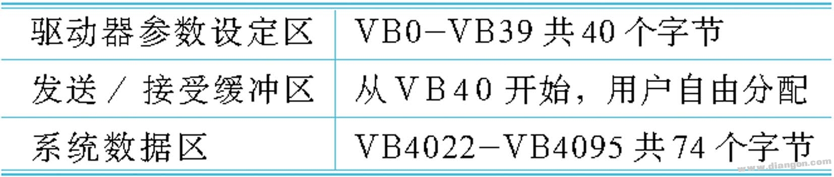
Driver parameter setting area VB0-VB39 A total of 40 bytes of transmission/reception buffer starts from VB40, the user freely allocates system data area VB4022-VB4095 for a total of 74 bytes, among which the driver parameter setting area mainly completes the number of slave stations (VB0) , each slave LAE length setting (VB1-VB31), broadcast transmission mode LAE (VB33) length, transmission time (VW34), initial transmission/reception buffer first address (VD36) (set value is VB40-VB4021) Where V is variable, B is a byte, W is a word, and D is a double word.
3.3 User Data Area Setting In the USS protocol, each slave station needs 44 bytes, and the send/receive buffers each occupy 22 bytes (corresponding to the slave station + USS protocol (send + accept) + status bit), where the status The bit indicates the data transmission status. In this system, the transmission/reception first address is set to VB2000, and the user data area is allocated as follows when transmitting data in a round-robin manner:
Winch: slave station 1, address VB2000-2043
A frequency converter of mud pump 1: slave station 2, address VB2044-2087
B inverter of mud pump 1: slave station 3, address VB2088-2131
A frequency converter of mud pump 2: slave station 4, address VB2132-2175
B inverter of mud pump 1: slave station 5, address VB2176-2219
The address when sending data by broadcast is as follows:
Only the send buffer: VB2220-2263, after accepting the buffer as defined above, you can complete the control function according to the function of each address and write the corresponding control word during plc programming.
3.4 Communication function setting When the CPU is in STOP mode, the free port mode is disabled, communication with other protocols is established. Only when the CPU is in RUN mode, the free port mode can be used. At this time, the free port control word SMB30 is used to complete the setting. For example: MOVB16#49, SMB30 sets free port 0 to free port protocol, baud rate is 9600kbps, data bit is 8, even parity.
4 The programming system function consists of the main program OB1 and three subroutines SBR0, SBR1 and SBR2. Figure 2 shows the workflow of the main program segment.
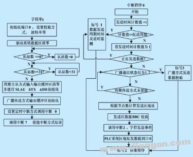
Figure 2 Working flow chart of the main program block
(1) OB1: Complete loop call subroutine function
(2) SBR0: system initialization
(3) SBR1: Communication interrupt/event call (interrupt 0~interrupt 7, complete data transmission and reception according to communication protocol)
(4) SBR2: Write the function program according to the previous assigned address and the function to be realized, realize the logic function, digital filtering, PI adjustment, and read and write of the inverter parameters, control word and speed reference between the required input and output signals. The transmission, the reading of the working state of the inverter and other functions.
(5) Interrupt 0: Complete initialization of transmission/broadcast, monitor transmission process, monitor transmission delay, send error
(6) Interrupt 2: Send completed
(7) Interrupt 3~6: After receiving the basic receive buffer, checksum is performed, and the checksum data block is sent to the data receiving buffer of the current station.
(8) Interrupt 7: Accept any character for more than the time, execute interrupt 7, perform a status reset, and end the interrupt.
5 Inverter setting Inverter selects MASTERDRIVER 6SE71 series engineering inverter, working motor is squirrel-cage three-phase asynchronous AC variable frequency motor produced by Yongji Motor Factory. The inverter control mode adopts vector control control and load mode selection. As standard, it can be used after motor identification by inverter. The communication interface corresponds to X101 terminal 10 (RS485P), 11 (RS-485N) on the interface board CUVC, motor start and stop control bit P554.1=6100, the remaining control bits (parking mode, direction of rotation, etc.) and so on. P734.1~16 reads the connection word address number of the motor parameter to be collected in the inverter; P918.0/slave address and PLC setting are consistent; P053=34(PMU+SST2); The ten digits must be 1 to activate the communication; then the control word and the given signal sent by the communication are sent to the interface address...; and the terminating resistor is connected at the beginning and the end of the bus.
At the same time, in order to reduce electromagnetic interference, a shielded twisted pair cable is used, wherein the shielded wire is grounded at one end.
6 Conclusion Through the use and comparison, the USS free port communication can realize the access of the inverter data without any additional board, and the communication quality is high, and the automation system is realized at a low cost. This greatly reduces development and engineering costs, and reduces the electrical complexity of the system compared to previous relay controls (many logic and protection functions are achieved by interlocking between relays, complex implementation, high failure rate, overhaul time) Long), at the same time, the logic performance of the system is greatly improved, the reliability of the product is improved, and the downtime caused by electrical failure is reduced.
KNB1-63 Miniature Circuit Breaker
KNB1-63 Mini Circuit breakers, also named as the air switch which have a short for arc extinguishing device. It is a switch role, and also is a automatic protection of low-voltage electrical distribution. Its role is equivalent to the combination of switch. Fuse. Thermal Relay and other electrical components. It mainly used for short circuit and overload protection. Generally, According to the poles, mini Circuit breaker can be divided into 1P , 1P+N , 2P, 3P and 4P.
KNB1-63 Miniature Circuit Breaker,Electronics Miniature Circuits Breaker,Automatic Miniature Circuit Breaker,Mini Circuit Breaker
Wenzhou Korlen Electric Appliances Co., Ltd. , https://www.zjmotorstarter.com