- Model NO.: XRNT3A(ZLR10)-12/16~125-50kA
- Type: Current Fuse
- Shape: Insert
- Standard: UL
- Transport Package: Carbon
- HS Code: 8535100000
- Breaking Capacity: High
- Usage: High Voltage
- Fusing Speed: FF
- Trademark: zhenli
- Origin: Shaanxi Xi′an
Normal operating conditions
1) Maximum ambient air temperature is 40ºC and the lowest is -40ºC;
2) Altitude is not more than 1000m;
3) Relative humidity: daily average is not more than 95%, and the monthly average is not greater than 90%;
4) Surrounding air is not excessively polluted by the dust, smoke, corrosive or flammable gas, steam or salt fog;
5) When the fuse is used in transformer oil, the ambient temperature of transformer oil shall not exceed 105ºC.
Model description
Â
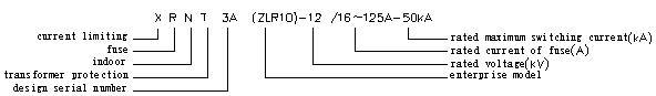
 (Note: "/S" after the rated current means the blown fuse indication and signal output functions, and "/H" after "S" means the application to high-altitude products, i.e. H1 means the altitude greater than 1000m and less than or equal to 2000m, H2 means the altitude greater than 2000m and less than or equal to 3000m and H3 means the altitude greater than 3000m and less than or equal to 4000m)
Basic parameters
| Model | Rated Current of Fuse (A) | Rated Current of Fuse Link (A) | No. | Rated Voltage (kV) | Rated Maximum Breaking Current (kA) |
|
XRNT3A-12 (ZLR10-12) |
100 | 16, 20, 25, 31.5, 40, 50, 63, 80, 100 | Fig.1 | 12 | 50 |
| 125 | 125 | Fig.2 |
Outline and installing dimensions of fuse are as shown in Fig. 1 and Fig. 2.
Â
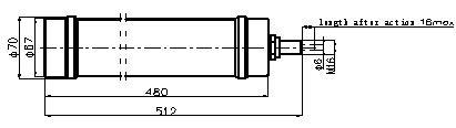
 Fig. 1 a) Outline drawing of XRNT3A(ZLR10)-12/16~100A fuse link
Â
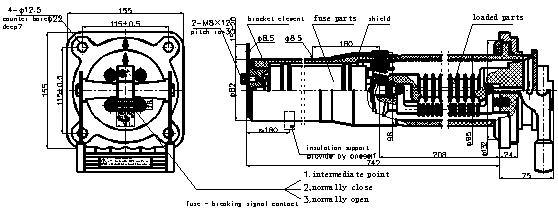
Fig.1 b)Â Outline and installing dimensions of XRNT3A(ZLR10)-12/16~100AÂ fuse
Â
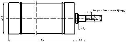
Fig.2 a)Â Outline drawing of XRNT3A(ZLR10)-12/125AÂ fuse link
Â

Fig.2 b)Â Outline and installing dimensions of XRNT3A(ZLR10)-12/125AÂ fuse
Main technical data
The fuse under specified operating conditions is able to reliably break any fault current from the minimum fusion current to the rated breaking current 50kA.
Fuse is of the plug-in structure and consists of the fuse link, fuse element carrier and bracket shell.
The temperature of transformer oil around the fuse shall not exceed 105ºC, and when the ambient temperature is higher than 40ºC, the fuse shall derate by 1% for every 1ºC rise.
Â
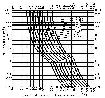
Fig.3 time-current characteristic curve
Installation and use description:
The specifications of mounting holes of fuse on the transformer box are as follows: φ100+1.5   0(16~63A),φ120+1.5   0(63~80A). Four M10×45 mm bolts (M10 blind screw hole) are arranged around the round hole with the spacing between the bolts (screw holes) as 115×115±0.5(16~100A) and 130×130±0.5mm (125A), and the positions of four bolts (screw holes) are concentric with the mounting holes;Â
After the fuse is mounted into the box, the adequate insulation distance shall be maintained between the outer skins of fuse bracket shell and between the outer skin of bracket shell/ends and the inner wall of transformer oil tank/out-phase cable;
Fuse is installed horizontally and is perpendicular to the panel of transformer box. The part of fuse into the tank shall be immersed in the transformer insulation oil and reliably supported with the insulation bracket (supplied by user, see Fig.1 and Fig. 2).
Installing steps:
1. The insulation bracket shall be (supplied by user) installed in the transformer box according to Fig.1 and Fig. 2, or the fuse is prone to sag due to the self weight, causing the uneven force between the sealing ring and panel or breakage at the root of fuse bracket flange, thus leading to the oil spill.
2. Fit the sealing ring into the fuse bracket and through the corresponding hole on the box to make the fuse bracket perpendicular to the box panel, and tighten four fixing nuts, and then tighten the insulation bracket with the nylon cable ties or insulation tape.
3. Connect the front and rear terminals of fuse in series to the return conductor, and tighten the screws moderately;
4. Before inserting the fuse link, check the threaded connection between the fuse link and fuse element carrier for looseness. Fuse link metal cap surface and the conductive contact surface of fuse element carrier shall be clean. Then make the arrow direction on the lid of fuse element carrier aligned with that on the aluminum gland. Hold the handle and fuse link respectively with one hand each and insert it lowly into the fuse bracket, and then pull down the handle to lock it.
5. Connect the intermediate, normally-close and normally-open contacts on the lid.
Rational use:
1. The rated current of fuse link is from 16A to 125A, and the greater rated current may be achieved through the double-parallel mode.Â
2. When replacing the fuse link, do not switch to on-load circuit when it is uncharged;
3. For the three-phase system, w hen the fuse of one phase acts, generally replace all three phases unless you can confirm that the fault current passes through one phase. In the replacement of fuse link, the fusion tube getting yellow or darker is normal.
Selection of fuse
| General Principle for Fuse Selection | ||||||||||
|
Rated Voltage  (kV) |
Rated Capacity of Transformer (kVA) | |||||||||
| 160 | 200 | 250 | 300 | 400 | 500 | 630 | 800 | 1000 | 1250 | |
| Rated Current of Fuse (A) | ||||||||||
| 12 | 16 | 20 | 25 | 31.5 | 40 | 50 | 63 | 80 | 100 | 125 |
Bolted Silo,Grain Dryer Co., Ltd. , http://www.nsgraindryer.com