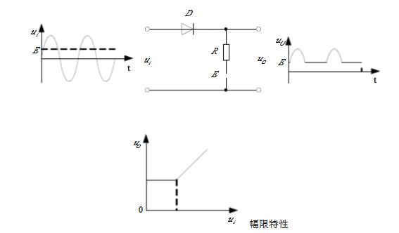
Limiting circuit 
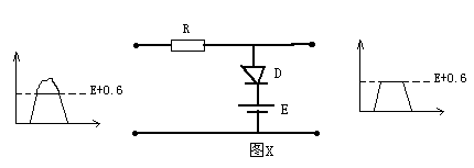
Figure X is a limiter circuit. When there is no signal input at the input terminal, the output voltage is zero because the diode D is connected in reverse. When there is a pulse signal input, if the amplitude of this pulse is enough for the voltage source E, D is turned on, so that the circuit limits the maximum value of the output pulse to E + 0.6 (0.6 is the forward voltage drop of D), also That is, E + 0.6 is the threshold voltage of this limiter.

Follow WeChat

Download Audiophile APP

Follow the audiophile class
related suggestion
The most basic working state of the diode is on and off, using this feature can form a limiting circuit. The so-called limiting circuit refers to the limiting circuit ...
The series input limiting circuit consists of power supply VCC, resistors R1, R2, R3, switching diodes D1, D2, capacitors C1, C2 ...
The function diode of the lower limit limiting circuit circuit with accurate limiting level plus reverse bias, namely
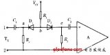
FM radio limiter circuit
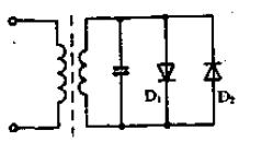
Limiting circuit formed by voltage stabilizing diode
'+ data.data.username +' '; dom + ='
Ac Contactor,Contactor For Ac Unit,Compressor Contactor,Air Conditioner Contactor
NanJing QUANNING electric Co.,Ltd , https://www.quanningtrading.com