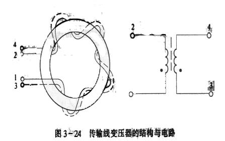
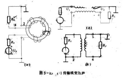
The advantage of resonant high-frequency power amplifier is high efficiency. However, tuning is very cumbersome, and the tuning speed is slow, which cannot meet the requirements of the development of modern communications. For transmitters that require fast frequency conversion in multiple channels; transmitters with fast frequency hopping technology in electronic countermeasure systems; transmitters composed of multi-channel frequency synthesizers, etc., all require fast-tuning and tracking amplifiers. Obviously, the resonant high-frequency power amplifier cannot meet the requirements. Therefore, the application of broadband amplification technology in high-frequency amplification is very important. The frequency band of the wide-band high-frequency power amplifier can cover the entire operating frequency range of the transmitter, so no tuning is required when the transmitter changes its operating frequency. 1. Characteristics and principles of high-frequency transmission line transformers Transmission line transformer is a new component developed on the basis of transmission line and transformer theory. It uses a ferrite material with good high frequency performance and high permeability as the magnetic core, and is formed by winding double insulated wires evenly on a ring-shaped magnetic core of rectangular cross section, as shown in Figure 3-24. The diameter of the magnetic ring is determined according to the transmitted power and the size of the required inductance. Generally, the core material is (10-30) mm. The core material is divided into manganese zinc and nickel zinc. When the frequency is higher, the nickel zinc material is suitable. The structure of this kind of transformer is simple, light, cheap, and the frequency band is very wide (from a few kilohertz to a few hundred megahertz). Figure 3-25 is a schematic diagram of a 1: 1 transmission line transformer. It can be seen from the figure that it is to close two wires of equal length together, and the two wires are wound around the magnetic ring. The wiring method is shown in Figure 3-25 (α). Figure 3-25 (b) is the equivalent circuit of the transmission line. The signal voltage is added to the transmission line transformer from the 1 and 3 terminals, and the energy is fed to the load at the 2 and 4 terminals through the transmission line transmission. Figure 3-25 (c) is the circuit form of a common transformer. Since the 2 and 3 ends of the transmission line transformer are grounded, this transformer is equivalent to an inverter. In fact, the transmission line transformer and the ordinary transformer transfer energy in different ways
Same. For ordinary transformers, the signal voltage is applied to the first and second ends of the primary winding, so that the primary coil has a current flow, and then through the magnetic field line, the corresponding alternating voltage is induced at the secondary 3 and 4 ends, and the energy is transferred from the primary To the secondary load. However, the signal voltage of the transmission line is applied to the terminals 1 and 3, and the energy propagates in the medium between the two wires, and reaches the load on the output from the input.
For the transmission line, it can be regarded as a coupling chain composed of many inductances and capacitances, which is at the bottom, as shown in Figure 3-26. The inductance is the inductance of the wire ΔL, and the capacitance is the distributed capacitance between the two wires. When the signal source is added to terminals 1, 3, due to the presence of the capacitance between the transmission lines, the signal source charges the electricity and the capacitance, so that the capacitor stores the electric field energy. The capacitor discharges near the inductor to make the inductor store magnetic field energy. That is, electric field energy can be converted into magnetic field energy. Then the inductance exchanges energy to the capacitor behind, and the magnetic field energy is converted into electric field energy. Then, the capacitor exchanges energy with the inductance in the back, and so on. The input signal is transmitted in the form of electromagnetic energy exchange from the beginning to the terminal, and finally absorbed by the load. In the transmission line transformer, the distributed capacitance between the lines is not an unfavorable factor affecting high-frequency energy transmission, but rather an indispensable condition for electromagnetic energy conversion. In addition, electromagnetic waves mainly propagate in the medium between the wires, so the loss of the magnetic core greatly reduces the signal transmission. The maximum operating frequency of the transmission line transformer can be greatly improved, so as to achieve the purpose of broadband transmission. Strictly speaking, transmission line transformers transmit energy in different ways at high and low frequency bands. At high frequencies, it is mainly transmitted by means of electromagnetic energy transformation. At low frequencies, it will be transmitted simultaneously through the transmission line and magnetic coupling. The lower the frequency, the worse the efficiency of the transmission line to transmit energy, and the more it depends on the magnetic coupling method for transmission. Second, the broadband transmission line transformer circuit (1) 1: 1 transmission line transformer The transmission line transformer shown in Figure 3-25 is called a 1: 1 transmission line transformer, also known as an inverter transformer. According to the transmission line theory, when the transmission line is a lossless transmission line and the load impedance RL is equal to the transmission line characteristic impedance Zc, the relationship between the transmission line terminal voltage U2 and the starting terminal voltage Ul is ↠U 2 = Ul e -jωt In the formula, α = 2π / λ is the phase shift constant of the transmission line, the unit is rad / m. It is the operating wavelength, and t is the length of the transmission line. If the length of the transmission line is very short, satisfying αl <1, then e-jωt≈1, then U 2 = U 1, that is, the amplitude of the voltage U of the input end of the transmission line is equal to the voltage U 2 of the output end, and the phase is approximately the same. In the same way, I 2 = I le -jωt and I 1 = I 2 is necessary. Under the condition that the 2 and 3 terminals are grounded, a voltage with the same amplitude and opposite phase as the input terminal is obtained on the load RL, that is UL = -UI It can be seen from the circuit diagram that the conditions for matching transformer and fu are: Zc = RL, The conditions for matching the signal source to the transmission line transformer are ZC = Rs Obviously, the best matching condition for 1: 1 transmission line transformers is Zc = Rs = RL The power obtained on the load RL is Po = I 2 RL And I l = I 2, then Po = I 2 RL = [Us / (Rs + Zc)] 2R L Under the condition of RL = Zc = Rs, the maximum power can be obtained on RL. (2) 1: 4 impedance transformation transmission line transformer 1: 4 transmission line transformer. It can function as a 1: 4 impedance converter, that is, Rs: RL = 1: 4. The following only illustrates the optimal matching conditions and the relationship of impedance transformation on the relationship between the voltage and current of the ideal, lossless transmission line. Since the lossless transmission line is under matching conditions, U l = U 2 and I 1 = I 2, then Z i = U 1 / I 1 + I 2 = U 1 / 2I 1 = Zc / 2 In addition RL = U 1 + U 2 / I 2 = 2U 1 / I 1 = 2Z C Therefore, under the best matching conditions, the transmission line transformer Rs = Zi = Zc / 2 = RL / 4 is equivalent to a 1: 4 impedance converter. (3) 4: 1 impedance transformation transmission line transformer According to the master of 4: 1 impedance transformation, the circuit shown in Figure 3-28 can be used to form. Below we still use the relationship between the voltage and current of the ideal element loss transmission line to illustrate the optimal matching conditions and the relationship of impedance transformation. Since the lossless transmission line is under matching conditions, U 1 = U 2 and I 1 = I 2 Z i = UI + U 2 / I 1 = 2U 1 / I 1 = 2Zc In addition, RL = U 2 / I 1 + I 2 = U 1 / 2I 1 = 1/2 Zc Therefore, under the best matching conditions, Rs = Zi = 2Zc = 4R L. 3. Broadband high frequency power amplifier A broadband high-frequency power amplifier drawn by a transmission line transformer and a transistor uses a transmission line transformer to transmit high-frequency energy in a wide frequency band and achieve impedance matching between the amplifier and the amplifier or between the amplifier and the load. Figure 3-29 is a typical circuit of this power amplifier. B1, B2 and B3 are wide-band transmission line transformers. Bl and B2 are connected in series to form a 16: 1 impedance converter to match the high output impedance of Tl with the low input impedance of T2. Each stage of the circuit uses a negative voltage feedback circuit to improve the performance of the amplifier. Resistors 1.8KΩ and 47Ω connected in series provide feedback to the T1 amplifier, and resistors 1.2KΩ and 12Ω connected in series provide feedback to the T2 amplifier. In order to avoid the parasitic coupling between the amplifier stages through the internal resistance of the power supply, the RC decoupling filter circuit is used. The filter capacitor is composed of three capacitors of different sizes connected in parallel to filter different frequencies. Since no tuning loop is used, this amplifier should work in Class A state. Class B push-pull circuits are used for the input to improve efficiency. The operating frequency range of this circuit is (2-30) MHZ, and the output power is 6OW. According to the load of 50Ω, after the 4: 1 impedance transformation of B3, the collector load of T2 is 200Ω. Since it works in a high power state, its input resistance is about 12Ω, and it will change with the size of the input signal. In order to reduce the influence of the input impedance change on the pre-amplifier, a 12Ω resistor is connected in parallel to the input end of T2, so that the total input resistance becomes 6Ω. After the 16: 1 impedance transformation, the collector load of T1 is 96Ω . |

Follow WeChat

Download Audiophile APP

Follow the audiophile class
related suggestion
Avago Introduces New High Linear Power Amplifier Module Product Avago Technologies ...
The circuit is shown in Figure 1. The chip IC uses the LM1875 of the American NS company, which has a soft tone and low distortion (0.015% ...
The word "Monster" has both positive meaning and ...
When the output power of the digital power amplifier is greater than 50W, it is impossible to use only ...
If an "audiophile" is a group of people who are never satisfied with the sound and "loved the new and the old" with the audio equipment. Then just rely on these so-called "fever spirits" ...
First, the circuit principle and characteristics 1. Power amplifier part (see Figure 1)
There is a well-known saying in the Hi-Fi world that is "briefness first." This means that if ...
Simple and practical TDA2822M integrated power
TDA2030 is ...

STK465 thick film ...

This RF power amplifier can output 2-3 channel signals, covering an area of ​​about one square kilometer, is ...
![[Photo] 15w RF power amplifier](http://i.bosscdn.com/blog/20/06/41/521040781.gif)
Low frequency power amplifier
![[Photo] TDA2030 audio power amplifier](http://i.bosscdn.com/blog/20/06/41/5131012891.gif)
Looking at the Hi-Fi amplifiers currently on the market, the output power is 100W ...
![[Photo] Transistor 15W Class A Power Amplifier](http://i.bosscdn.com/blog/20/06/41/513102891.gif)
With the newly launched LM4651 and LM465 from National Semiconductor ...
![[Photo] 125W Class D Subwoofer Power Amplifier](http://i.bosscdn.com/blog/20/06/41/513100868.jpg)
![[Photo] Mark Levinson No. 30 ...](http://i.bosscdn.com/blog/20/06/41/513544752.jpg)
EL34 (6CA7) was first launched by Philips in 1956 ...
![[Photo] 45W transistor tube hybrid power amplifier](http://i.bosscdn.com/blog/20/06/41/513531952.jpg)
This article cleverly combines the electronic tube EL34 and the transistor (op amp), ...
![[Photo] 32W hybrid audio power amplifier](http://i.bosscdn.com/blog/20/06/41/513526493.jpg)
The pre-amplifier adopts a European-made TESLA brand low noise high cheek double transistor ...
![[Photo] Gallstone hybrid power amplifier using switching power supply](http://i.bosscdn.com/blog/20/06/41/513524776.gif)
"Simple" means the circuit of the amplifier is simple, making it easier, as long as the picture ...
![[Photo] Simple fool power amplifier](http://i.bosscdn.com/blog/20/06/41/513432946.jpg)
1. Description: & nb ...
![[Photo] LM386 low voltage audio power amplifier ...](http://i.bosscdn.com/blog/20/06/41/513417261.gif)
The Class A transistor power amplifier has a warm and sweet tone, which makes people tempted. But the temperature rise of Class A amplifier ...
![[Photo] Class A power amplifier using SAP15N / P audio pair tube ...](http://i.bosscdn.com/blog/20/06/41/513346769.gif)
The circuit is shown in Figure 5, ...
![[Photo] Using TDA7294 and 2SA1216 / 2S ...](http://i.bosscdn.com/blog/20/06/41/4233420295.gif)
'+ data.data.username +' '; dom + ='
Female Header,Female Header Pitch 2.54Mm,Smt Female Header,In-Line Patch Female Connector
Shenzhen Jinyicheng Electronci Technology Co.,Ltd. , https://www.jycconnector.com